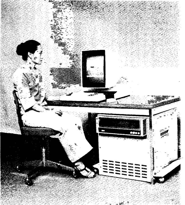
Figure 1. The Alto personal computer, showing a
user at work with the display, mouse, and keyset.
This document was made by
OCR from a scan of the technical report. It has not been edited or proofread
and is not meant for human consumption, but only for search engines. To see the
scanned original, replace OCR.htm with Abstract.htm or Abstract.html in the URL
that got you here.
Alto: A personal
computer
by C. P. Thacker, E. M.
McCreight, B. W. Lampson, R.
F. Sproul!, and D. R. Boggs
CSL-79.11 August 7, 1979; Reprinted February 1984.
©
Copyright 1979 by Xerox Corporation. All rights reserved.
Abstract:
The Alto is a small computer system designed in early 1973 as an experiment in personal computing. Its principal
characteristics, some of the design choices that led to the implementation, and some of the applications for
which the Alto has been used are discussed.
This paper appeared in
Siewiorek, Bell and Newell, Computer Structures: Principles and Examples, second edition, McGraw-Hill, New York, pp.
549-572.
CR categories: 6.21, 8.2
Key words and phrases: personal computer, graphics, local network
1. Introduction
During early 1973, the Xerox Palo Alto Research Center designed the Alto
computer system ("Alto") as an experiment in personal computing, to
study how a small, low-cost machine could be used to replace facilities then
provided only by much larger shared systems. During the succeeding six years,
the original Alto underwent several engineering enhancements to increase its
memory capacity and reduce its cost, but the basic capabilities of the system
have remained essentially unchanged.
There are now (summer 1979) nearly a thousand Altos in regular use by computer science researchers, engineers, and secretaries.
The
primary goal in the design of the Alto was to provide sufficient computing
power, local storage, and input-output capability to satisfy the computational
needs of a single user. The standard system
includes:
·
An 875 line raster-scanned
display.
·
A keyboard,
"mouse" pointing device with three buttons, and a five-finger keyset.
·
A 2.5 Mbyte cartridge disk
file.
· An interface to the Ethernet system
("Ethernet"), a 3 Mbit/second communication facility.
§
A
microprogrammed processor that controls input-output devices and supports emulators for a number of instruction sets.
'
64K 16-bit words of
semiconductor memory. expandable to 256K words.
All of
these components with the exception of the user terminal are packaged in a
small cabinet which is an
unobtrusive addition to a normal office. The terminal, keyboard, and pointing
device are packaged for desktop use (Figure 1).
The
Alto has led to an entirely new computing environment. Many applications devote
the entire machine to
interacting with a user and satisfying his needs; examples are document production and illustration, interactive
programming, animation, simulation, and playing music. These individual applications are supplemented by a large number of
services available via communications;
examples are printing service, mailbox services for delivering electronic mail,
and bulk file storage services. The
Ethernet has also given rise to applications that use several Altos concurrently
to furnish additional computing power or to allow several people at their
machines to interact with one another.
The
principal characteristics of the Alto processor are described in Section 2.
Sections 3 to 6 describe input-output
controllers for the display, disk, Ethernet, and printer. Section 7 surveys the
environment and applications that grew up for
the Alto. Section 8 offers a brief retrospective look at the design.
Figure 1. The Alto personal computer, showing a
user at work with the display, mouse, and keyset.
2. The Alto processor
The major
applications envisioned for the Alto were interactive text editing for document
and program preparation, support for the program development process,
experimenting with real-time animation and
music generation, and operation of a number of experimental office information systems. The hardware design was strongly affected
by this view of the applications. The design is biased toward
interaction with the user, and away from significant numerical processing:
there are extensive user input-output
facilities, but no hardware for arithmetic other than 16-bit integer addition
and subtraction.
The processor is microcoded, which permitted the machine to start out
with rather powerful facilities, and also allows easy expansion as new
capabilities are required. The amount of control store provided has evolved over time as shown in Figure 2.
Initially, the machine contained only 1K words, implemented with PROM. The
most recent version provides 4K words, of which 1K is implemented with PROM, and
3K is RAM.
|
Year |
Main
Memory |
Control
Memory |
Processor Memory |
|||
|
Size |
Technology |
Size |
Technology |
Size |
Technology |
|
|
1973 |
64K Parity |
1K x 1 Dynamic Metal gate PMOS |
1K PROM |
256 x 4 |
32 R registers |
16 x 4 |
|
1 974 |
1K PROM 1K
RAM |
PROM as above |
32 R registers 32 S registers |
16 x 4 |
||
|
1975 |
64K Error Correction |
4K
x 1 Dynamic Si gate NMOS |
||||
|
1976 |
2K PROM 1K RAM |
1K x 4 PROMs Schottky bipolar RAM as
above |
||||
|
1977 |
256K |
16K x 1 Dynamic Si gate NMOS |
||||
|
1979 |
1 K PROM 3K RAM |
PROM as
above |
32 R registers |
R regs as above |
||
Figure 2. Sizes and
technologies used for the principal memories in the Alto.
The micromachine is shared by sixteen fixed priority tasks. The emulator, which interprets instructions of the user's program, is the lowest priority task; the
remaining tasks are used for the microcoded
portions of input-output controllers and for housekeeping functions. Control of
the micromachine typically switches from one
task to another every few microseconds, in response to wakeup requests generated by the rio controllers. The emulator task
requests a wakeup at all times, and runs if no higher priority task requires the processor. There is
usually no overhead associated with
a task switch, since the microprogram counters (MPCs) for
all tasks are stored in a special high speed RAM, the MPC RAM. The main memory is
synchronous with the processor, which controls all memory requests.
The
task switching mechanism provides a way of multiplexing all the system
resources, both processor and memory cycles, among the consumers of these
resources. In most small systems with single-ported memories, the memory
is multiplexed among the I/0 controllers and the CPU, and when an 1/0 controller is accessing the
memory, the CPC is idle. In the Alto, the processor is multiplexed, and
multiplexing of the memory is a natwal consequence. By sharing the hardware in this way, it has been possible to provide more
capable logical interfaces to the Ito devices than are usually found in small machines, since the 1/0
controllers have the full processing capability and temporary •storage of the micromachine at their disposal.
The
standard Alto contains controllers for the disk, the display, and the Ethernet.
The disk controller uses
two tasks. the display and the cursor use a total of four tasks, and the
Ethernet uses one task. In
addition to the emulator task, there is a timed task that is
awakened every 38 /Is, and a fault
task that is awakened
whenever a memory error occurs and is responsible for logging the error and generating an interrupt. The timed task
refreshes the main memory, and maintains the real-time clock and an interval timer accessible from the emulator.
The main memory size of the
Alto was initially 64K 16-bit words, implemented with 1K bit semiconductor RAM chips.
As semiconductor technology improved, the memory size was increased, as shown in Figure 2. The initial version of the
machine provided parity checking; later configurations employ single error correction and double error
detection. Memory access time is 850ns
(five microinstruction cycles), and either one or two words can be transferred
during a single memory cycle. In machines
with more than 64K, access to extended memory is provided via bank registers
accessible to the
micromachine; the standard instruction set and I/0 controller
microcode make use of the
additional' memory only in limited ways. The reason for this clumsy
arrangement is that the
lifetime of the Alto has been longer than originally anticipated, and the
additional memory was an unplanned addition.
Because
the machine was intended for personal use, protection and virtual memory facilities
normally included to support sharing were
omitted from the Alto.
The
multitasking structure of the processor led to an extremely simple
implementation. The processor is contained on five printed circuit boards, each
of which contains approximately 70 small and medium-scale TIT integrated circuits. Each of the three standard I/0 controllers occupy a board with about
60 ICS. The main
memory uses 312 chips.
2.1 Emulators
There are emulators for several instruction sets, including BCPL [Richards], Smalltalk [Kay, Ingalls]. Lisp [Deutsch], and Mesa [Mitchell et
al]. The BCPL emulator is contained in the PROM microstore, while
the others are loaded into RAM
as needed. The BCPL instruction set was chosen because it is straightforward to implement and because we had previously
developed a BCPL compiler for a similar instruction set. BCPL is a typeless implementation language; it has much in common with its well-known descendant, C [Ritchie
et al]. The language was used extensively to build Alto
software; very little assembly language code has been written for the Alto.
The
BCPL instruction set and the virtual machine it
provides are summarized in Figure 3. Instructions
are divided into four groups:
M-Group
instructions transfer 16-bit words between memory and one of the four accumulators ACO-AC3. These instructions provide four indexing modes, and one level of indirection is allowed. The effective address is a
16-bit quantity, allowing access to a 64K word address space.
J-Group
instructions include unconditional and subroutine jumps, and two instructions
that increment and decrement a
memory location and test the resulting value for-zero. The effective address for these operations is calculated in the same way
as for the M-Group.
A-Group
instructions provide register-to-register arithmetic operations, shifts by one
or eight places, and conditional skips based on the
result of the operation.
S-Group
instructions provide a number of functions that do not fit within the framework
of the first three groups.
Instructions are provided for loading, reading, and transferring control to special microcode in the writeable
microstore, operating the real time clock and interval timers, optimizing BCPL procedure calls, accessing the extended memory, and maintaining specialized data structures used by the display.
The BCPL emulator provides a vectored interrupt system
with 16 interrupt channels. There is no hardware support for interrupts; they are implemented entirely in
microcode. (Note that the interrupt
system is completely separate from the task-switching mechanism; the latter
multiplexes the micromachine,
while the former multiplexes the emulator.) When the microcode associated with
an I/O controller wishes to cause an interrupt, it ORS one or more bits into a micromachine register NIW (New Interrupts Waiting). If the i-th bit of NIW is set, an interrupt on channel i is requested. At the start of every macroinstruction, NIW is tested; if it is nonzero, and if the corresponding channel is active, the emulator's macroprogram
counter is saved in a fixed location in main memory and control is transferred to a location taken
from a sixteen word table that starts at a fixed location. Individual channels are made active by setting
bits in another fixed location. There are S-group instructions to enable and disable the entire interrupt system,
and to return control from an interrupt routine.
![]()
![]()
![]()
![]()
![]()
![]()
![]()
![]()
![]() M-Group
M-Group
|
|
|
|
|
|
|
|
T |
|
0 |
MFunc |
AC |
|
X |
|
D |
|
|
|
|
|
|
|
|
|
|
|
1:
AC • MEM[EfAd] 2:
MEM[EfAd) + AC J-Group |
Effective
Address Calculation: case
0: D case 1: PC + sign extended D case 2: AC2 + sign extended D case 3: AC3 + sign extended D if I /3 0 then EfAd *- MEM[EfAd] |
![]()
![]()
![]()
![]()
![]() 0: PC +
EfAd Jump)
0: PC +
EfAd Jump)
1:
Ac3 PC + 1. PC EfAd (Jump To Subroutine)
2:
MEM[EfAd] • MEM(EfAd) + 1, if MEM[EfAd] = 0 then Skip 3: MEM[EfAd] MEM[EfAd] - 1, if MEM[EfAd] =
0 then Skip
A-Group
|
1 |
I SrcAC i |
1 DestAC 1 |
II AFunc 11 |
1 SH I |
1 CY 1 |
NL |
fI1 Skip ft |
 Afunc:
0: DestAc + NOT SrcAc
1:
DestAc - SrcAc
2:
DestAc SrcAc + 1
3:
DestAc SrcAc
4:
DestAc q- DestAc + SrcAc
5:
DestAc DestAc • SrcAc
6:
DestAc DestAc • SrcAc -1 7: DestAc DestAc AND SrcAc
S-Group
|
1111 11111 0 1 1 SFunc Argument 111 11111/1 |
Memory
To DestAc if NL 0

![]()
![]()
![]() ACO
ACO
![]()
![]()
![]() Load if NL = 0
Load if NL = 0
![]() AC2
AC2
![]()
![]()
![]()
![]() AC3 I Carry
AC3 I Carry
SrcAcCarry 1 0 1 DestAc
1r
|
AFunc |
|
|
|
|
|
|
|
|
Cin |
|
|
|
|
ALU |
|
|
|
|
|
|
|
![]()
![]()
![]()
![]() SH Shifter (17
bits)
SH Shifter (17
bits)
![]() Skip I
Skip I
Skip Sensor I
Cresult
![]() Result
Result
![]() 16
16
Figure 3. Summary of the BCPL instruction set and its virtual machine.
2.2 Input-output
I/O devices may be connected to the Alto in one of three ways,
depending on the bandwidth required by the
device and on the degree to which the controller is supported by specialized microcode. The three methods of connection and the
level of the machine used to interface the hardware are summarized in
the matrix of Figure 4.
LOGICAL INTERFACE LEVEL
BCPL or Asm Emulator
or Timed Private Task
(Loads&Stores) Task
Microcode Microcode

|
Impact printer Prom programmer CPU debugger XY
input tablet Cassette Tape |
Stitch welder Low speed raster scanner raster printer |
|
|
Keyboard
• Keyset
' Console computer |
Terminal concentrator Modem
interface |
Medium speed raster scanner Console
computer |
|
|
Mouse
' Hardware
Multiplier |
Display' Disk ` Ethernet
' Arpanet High
speed raster printer Audio Modem
interface |
' Included in standard Alto
Figure 4. Schematic
illustration of input/output attachments used on the Alto.
Device controllers that require significant bandwidth, or exploit the
computational facilities of the micromachine, are
connected directly to the processor bus, and use one or more of the sixteen microcode tasks. The disk, display, and Ethernet
controllers, which are part of the standard Alto, are interfaced in this way. The controller for a
high-speed raster-scanned printer is an example of a non-standard vo controller
interfaced directly to the processor bus. These devices are described in detail
in later sections.
Processor
bus devices have one or more dedicated tasks that provide processing and
initiate all memory references for the device controller; the tasks communicate
with programs through fixed locations and
data structures in main memory, and through interrupts. By convention, the
second page of the address space is
reserved for communication with devices of this type. Since there is only one processor, data structures shared between I/0 controllers and programs can
be interlocked by simply not allowing task switches in critical
sections of device control microcode.
The amount of data buffering in a device controller, its
task priority, and the bandwidth of the device
trade off much as they do in systems which have DMA
controllers competing for memory access. The controller must have enough buffering so
that the wakeup latency introduced by higher priority
devices will not cause the buffer to over- or underrun before it can obtain
service. The disk, for example, has only one word of buffering (10ps at
1.5Mbits/sec), and is therefore the highest
priority task. The Ethernet requires more bandwidth, but since it has a 16-word
buffer, it can tolerate much greater
latency than the disk (87ps at 3Mbits/sec), and hence runs at low priority. The display requires the highest bandwidth but it also has
a 16-word buffer, so it can tolerate slightly more latency than
the disk (12.8 its at 20 Mbits/sec), and is therefore between the disk and
Ethernet in priority.
It is also possible to connect a device directly to the
processor bus without using a separate task.
The microcode of the timed task, normally used to refresh the memory, may be
modified to operate devices that
require periodic service. When this is done, the timed task microcode is run in
the writeable microstore. The mouse, a pointing
device that provides relative positioning information
by being rolled over a work surface, is operated by the timed task. At 38 ps
intervals, the mouse is interrogated
for changes in position, and two memory locations corresponding to the mouse x and y
coordinates are incremented or decremented when
a change occurs. Specialized devices may also be
operated directly by the emulator microcode; a hardware multiplier is an example of this type of device. An S-group instruction is
added in the writeable microstore that loads
the registers of the multiplier from the ACS, initiates the desired operation, and copies the results
back into ACS when the operation terminates.
Devices with less demanding bandwidth requirements, or
with computational requirements that can be
satisfied by an emulator program rather than by a microprogram, are interfaced
to the memory bus of the Alto. The advantage of this method is that no
special microcode is needed. Communication
between the hardware and a program is done using ordinary memory reference instructions, as in the PDP-11. The device
controller decodes the memory address lines and delivers or accepts data under control of a read/write
signal generated by the processor. The last two 256-word pages of the address
space are reserved by the hardware for this purpose. Since a memory access
requires five microinstruction cycles, these devices cannot transfer data as
rapidly as those connected directly to the processor bus, where the transfer is
controlled by the microinstruction and requires
only one cycle. In the standard Alto, the keyboard and keyset are examples of
devices handled in this way.
It is also
possible to provide special microcode for devices that interface to the memory
bus. A network gateway that connects 64
300-baud communication lines to the Ethernet has been implemented in this way. The scanner hardware
consists of a single bit of buffering for the output lines, and level conversion for the input lines.
Serialization and deserialization of eight-bit characters is done by microcode that is a part of the
timed task; characters are passed to a macroprogram via queues maintained in main memory by this microcode. The
macroprogram implements the higher level
communication protocols.
The
standard Alto provides a third method of connecting simple devices, the parallel 1/0
port. This is a memory bus device, and
consists of a single 16-bit register that can be loaded by a store instruction, and a set of 16 input lines that
can be read by a load instruction.
The device controller does
not occupy a card slot in the backplane, but is external to the machine, and
attaches via a cable
to a standard connector on the back of the machine, which in turn is wired to
the memory control board. A large number of devices have been connected to the
Alto through this simple interface,
'ncluding low speed impact printers. a PROM programmer, a stitchwelding machine for the fabrication of circuit boards, and several types of low-speed raster
printers. Most devices that use speed-insensitive
handshake protocols can be interfaced via the parallel I/0 port: such devices require neither specialized
hardware nor microcode.
2.3 Details of the micromachine—
control
The
microinstruction format of the Alto is shown in Figure 5, and the principal
data paths and registers
of the micromachine are shown in Figure 6. Each microinstruction specifies:
· The source of processor bus data (Bs).
·
The
operation to be performed by the ALU (ALUF).
§
Two special
functions controlled by the Fl
and F2 fields.
· Optional loading of the T and L registers (LT,
LL).
· The address of the next microinstruction (NEXT).
All microinstructions require one clock cycle (170ns) for their
execution. If a microinstruction
specifies that one or more
registers are to be loaded, this happens at the end of the cycle.
The Alto does not have an
incrementing microprogram counter. Instead, each microinstruction
specifies the least
significant ten bits of the address of its successor using the NEXT field in the
instruction. This successor
address may be modified by the branch logic or by the uo controllers.
There are special functions
to switch banks in the microstore, allowing access to the entire 4x,
address space. The address of the next microinstruction to be executed by each
of the 16 tasks
supported by the
micromachine is contained in the 16-word MPC RAM. This RAM is addressed by
the yrAsx.
register, which contains the
number of the task that will have control of the processor in
the next cycle. The MPC RAM value for the current task is updated every microinstruction cycle.
Execution of a microinstruction begins when the
instruction is loaded into the Microinstruction Register (HAIR) from the control store outputs. At this
time, the information on the NEXT bus
is written into the MPC RAM at the location addressed by the NTASK register.
This value is the address of
the next instruction; within a short time, it appears at the output of the MPC RAM, the next instruction is fetched from
the control store, and the cycle
repeats.
![]()
![]()
![]()
![]()
|
|
|
|
|||||
|
1 I I RSEL I I I I |
I I 1 ALUF I |
-1 BS |
1 1 F1 I |
1 1 F2 |
LL |
LT |
I NEXT 1 |
|
|
ALU Function a Bus |
Bus Source Function
1 Function 2 0: -R 0: 0: |
|||||
|
|
1: T |
1: R 1: MAR .- 1: Bus= 0? |
|||||
|
|
2: Bus OR T' |
2: .1 2: Task 2: L<O? ?
=> Branch condition: |
|||||
|
|
3: Bus
AND T |
3 S 3: Task Specific 3: L = 0? Next.9 Next.9 OR condition |
|||||
|
|
4: Bus
XOR T |
4: S 4: * L LSH 1 4: Next
* Next OR Bus |
|||||
|
|
5: Bus + 1• |
5: *MD 5: •LRSH1 5: AluCartr |
|||||
|
|
6: Bus •1• |
6:
Mouse 6: * L
LCY 8 MD * |
|||||
|
|
7: Bus + T |
7:
*IR[8:15] 7: • Constant 7: • Constant |
|||||
|
|
10: Bus
- T |
10-17:
Task Specific 10.17:
Task Specific |
|||||
|
|
11: Bus•T
- 1 |
|
|||||
|
|
12: Bus + T + l• |
|
|||||
|
|
13: Bus + Skip' |
|
|||||
|
|
14: Bus
AND T• |
• = > T is loaded from ALU |
|||||
|
|
15: Bus
AND T' |
result,
not from the Bus |
|||||
|
|
16: not
used |
|
|||||
|
|
17: not
used |
|
|||||
Figure 5. Alto
microinstruction format.
Conditional branches are implemented by ORing one or more bits with the NEXT address value supplied by the control store. The source of the
data to be ORed is usually specified by the F2 field; it may be a
single bit, for example the result of the BUS=0 test, or it may be several bits supplied on the NEXT bus 'by an vo controller or by specialized logic.
When the value consists of an
n-bit field, a 2°-way branch, or dispatch is
done. Because the next instruction is already being fetched while the instruction is being executed,
conditional branches and dispatches affect not the address of an instruction's immediate successor,
but the instruction following that one. It is possible to execute branches in successive instructions,
providing this pipelining is taken into account by the microprogrammer. This branching scheme constrains
the placement of instructions in the microstore,
but the constraints are satisfied semi-automatically by the microprogram
assembler.
![]()
![]()
![]()
![]()
![]()
![]()
![]()
![]()
![]()
![]()
![]()
![]()
![]()
![]()
![]()
![]()
![]()
![]()
![]()
![]()
![]()
![]()
![]()
![]()
![]()
|
|
|
CTASK |
|
||||||
|
--)01NTASK |
|
||||||||
|
|
|
|
|
|
RSEL
0.4 |
||||
|
|
|
|
|||||||
|
MIR |
|||||||||
|
PROM Control
Memory 1K - 2Kw x 32 |
BS[0:21 |
||||||||
|
ALUF-[0:31 |
|||||||||
|
LL |
|||||||||
|
|
|
/22 |
|
||||||
|
MPC 12 |
|
|
LT |
||||||
|
F1(0:3 |
|||||||||
|
|
/10 |
F210:3______________ |
|||||||
![]()
![]()
![]()
![]() RAM
RAM
Control Memory
![]()
![]()
![]()
![]()
![]() 11(•3Kw x 32
11(•3Kw x 32
![]()
![]()
![]()
![]() Next Address Bus (10 bits)
Next Address Bus (10 bits)
![]()
![]()
![]()
![]()
![]() ______ Priority
______ Priority
![]() Encoder _________ Wakeup
Requests (6 free)
Encoder _________ Wakeup
Requests (6 free)


![]()
![]()
![]()
![]() CTASK RSEL10:41
CTASK RSEL10:41
![]()
![]()
![]() L
L
BS10:21
![]() 256w x 16
256w x 16
![]() Processor Bus (16 bits)
Processor Bus (16 bits)
![]()
![]()

![]()
![]()
![]()
![]()
![]()
![]()
![]()
![]()
![]()
![]() P
P
![]()
![]() 0
0
![]()
![]()
![]() M
M
![]() 6
6
![]()
![]()
![]()
|
|
|
_30. |
Data Main Memory 64K • 256Kw x 16b error
corrected Address |
|
Data Memory Bus I/O Devices Address |
|
|
|||||
|
LL |
MAR |
||||
|
|
|||||
|
|
Decode and Control |
||||
|
|
|
||||
Task switching in the Alto is done by changing the value in the NTASK register. As long as the value in this register does not change, a task will remain in control of
the processor. A task gives up control of the processor by executing a
microinstruction containing FL-TASK.
This function loads the NTASK register from the output of a priority encoder whose inputs are the
16 wakeup request lines, one per task. An uo controller indicates
its need for service from the processor by asserting the request line associated with its task, If it is the
highest priority requester when the running microprogram executes the TASK function. NTASK will be loaded with its task number: after a one instruction delay, the new task will
acquire the processor. In the microinstruction following a TASK, a microprogram may
not execute a conditional branch, and it must not allow a task switch when it has state in the L or T registers, since none of the state of a task other than the MPC value is saved across a
task switch. With these exceptions, there is no overhead associated with task switching.
The
conditions that cause uo controllers to request wakeups are determined by the
controller hardware, and are
usually simple—an empty buPfer requires data, or a sector pulse has
been received by the disk controller, for example.
When the microcode associated with the controller has processed the request and commanded the controller to remove the wakeup
request, the microprogram then TASKS, relinquishing control of the processor.
By convention, eight of the possible values of the Fl and F2 fields of the microinstruction are task-specific; that is, they have different meanings depending on which
task is running. Each uo controller
can determine when its associated task has control of the processor by decoding
the NTASK lines. When the task associated with a
controller is running, the controller decodes the Fl and F2 lines and uses them to control data transfers, to
specify branch conditions, or for other device-specific
purposes. This encoding
reduces the size of the microinstruction.
The
intimate coupling between the micromachine and the uo controllers has proven to
be one of the most powerful
features of the Alto. When a new uo device is added, the controller not only has at its disposal the basic arithmetic and
control facilities of the micromachine, but it can also implement specialized functions controlled by the
task-specific function fields of the microinstruction. This has led to extremely simple hardware in the uo
controllers. Most control'ers consist
of a small amount of buffering to absorb wakeup latency, registers and
interface logic to implement the electrical protocols of the device, and a
small amount of logic to decode the Fl and F2 lines, generate wakeups, and do whatever high speed housekeeping is
required by the device. Since
the processor makes all the memory requests, controllers never manipulate
memory addresses, and the usual DMA hardware found in most minicomputers is
eliminated.
It might appear that sharing the processor in this
way would result in a significant degradation in performance, particularly for low priority tasks such
as the emulator. This is in fact not the case: the major bottleneck in the system is the memory. Since most computation can be overlapped with
memory operation, the performance of the Alto compares favorably with other
systems employing single-ported,
non-interleaved memory at comparable uo bandwidths.
2.4 Details of the micromachine—
arithmetic
The arithmetic section of
the Alto contains the following components:
A 16-bit processor bus,
used to transmit data between the subsections of the processor. the memory, and the I/0 controllers. The source of bus data is controlled by the BS and the Fl fields of
the instruction.
A bank
of 32 16-bit R registers, and eight banks of 32 16-bit S registers. These registers have slightly different properties, and together constitute the high
speed storage of the processor.
As better integrated circuit technology has become available, the number of S registers has been increased as shown in Figure 2. R and S are addressed by the RSEL field of the instruction; either R or s (but not
both) can be used during a single instruction. Reading and loading of R and s are controlled by the BS field of the instruction.
A
16-bit T register. T is loaded when the LT bit is set in the microinstruction. The source of T data is determined
by the ALU function being executed; it is usually the bus,
but may be the output of the ALE. T is one of the inputs of the
ALU.
A
16-bit Arithmetic/Logic Unit (ALE).
The ALU is implemented with four sN74s181 ics. These devices can
provide 64 arithmetic and logical functions, most of which are useless. The fourteen most useful functions are selected
by the four bit ALUF field of the microinstruction, which is mapped by
a PROM into the control signals required by the chips.
A
16-bit L register. L is loaded from the ALE output when the LL
bit is set in the microinstruction.
A
shifter capable of shifting the data from L left or right by one bit position
and exchanging the two halves
of a word. Simple shifts are controlled by the Fl field
of the instruction (F1=4. 5. 6). In
the emulator task, these functions may be augmented by the F2 field to do specialized shifts required by the BCPL instruction set, and to do double-length
shifts for microcoded multiply and divide.
A 16-bit Memory Address
Register (MAR), described later.
A 256
word by 16-bit constant memory, implemented with PROMS. This
memory is addressed by the
concatenation of the RSEL and BS fields of the
instruction; when Fl or F2 = CONSTANT, the
normal actions evoked by RSEL and BS are suppressed, and
the selected constant is placed
on the bus. Approximately 200 of the 256 available constants have been used.
An Instruction Register (IR) that holds the current macroinstruction being executed by the BCPL emulator.
The main
memory is synchronous with the processor, which initiates all memory references
by loading MAR with the 16-bit address of a location. During a memory reference, data
may be transferred between the memory and any register
connected to the bus, including registers in the i/o controllers. The memory can transfer a doubleword quantity during two
successive instruction cycles, as part
of a single memory cycle. Using this access method, which was provided to
support high performance peripherals such as the display, the peak memory
bandwidth is 32bits/(6*17Ons) = 31.3 Mbits/sec.
The
arithmetic section of the Alto contains a small amount of hardware to support
the emulator for the BCPL instruction set. There are special paths to supply part of the R address from the SrcAC and DestAC fields of IR, logic to dispatch on several fields in IR, and
hardware to control the shifter and
maintain the CARRY and
SKIP flags. The
total amount of specialized hardware is less than ten
No special hardware has been added to support emulators for other
instruction sets. These usually
specify the operation to be performed with a single eight-bit byte, followed by
one or two bytes that supply additional parameters for some of the operations.
The standard dispatching mechanism
is used to do an initial 256-way dispatch to the microcode that emulates each macroinstruction.
The
dispatching mechanism has been used for other applications. Although the
micromachine does not support
subroutine linkage in the hardware, it has been possible to achieve the same
effect with only a small
performance penalty. The calling microcode supplies a small constant as a return index (typically in T) which is saved and used as a dispatch
value to return to the caller when the subroutine
has completed its work. The Mesa emulator implements an eight word operand
stack by dispatching on the value of the
stack pointer into several tables of eight microinstructions, each of which
reads or writes a particular R-register.
The
parallelism available in the microinstruction format encourages the use of
complex control structures
which are often substituted for specialized data handling capabilities: it is
usually possible to do
an arithmetic operation, a branch or dispatch, and at least one special
function in each instruction.
3. User input/output
The main goals in the design of the Alto's user input/output were
generality of the facilities and
simplicity of the hardware. We also attached a high value to modeling the
capabilities of existing
manual media; after all, these have evolved over many hundreds of years. There
are good reasons for most
of their characteristics, and much has been learned about how to use them effectively. The manual media we chose as models
were paper and ink (the display), pointing devices (the mouse and cursor), and
keyboard devices ranging from typewriters to pianos and organs.
3.1 The display
The most
important characteristic of paper and ink is that the ink can be arranged in
arbitrarily chosen patterns on the paper;
there are almost no constraints on the size, shape or position of the ink
marks. This flexibility is used in a number of ways:
Characters of many shapes and styles not only represent
words, but convey much important
information by variations in size and appearance (italics, boldface, a variety
of styles).
Straight lines and curves
make up line drawings
ranging in complexity from a simple business form to an engineering drawing of an automatic transmission.
Textures and shades of gray, and color, are used to organize and highlight information, and to add a third to the two dimensions of
spatial arrangement.
Halftones make it
possible to represent natural images which have continuous tones.
Fine-grained positioning
in two dimensions produces effects ranging from
the simple (superscripts, marginal notes,
multiple columns) to the complex (mathematical formulas. legends in
figures).
The high resolution of ink, combined with the absence of positioning
constraints, means that a
large amount of information can be presented on a single page.
In
addition to imaging flexibility, paper and ink have several other important
properties: Large sizes of paper can present the spatial relationships
of many thousands of objects.
Many sheets of paper can be spread out, so that many pages can be wholly or partially visible.
Many sheets of paper can be
bound together, so that one item from a very large collection of information can be examined within a small
number of seconds.
Only one technique is known for approximating all these properties of paper in a computer-generated medium: a raster display in which the value of
each picture element is independently stored as an element in a two-dimensional array called a bitmap or frame buffer. If the size of a picture element is small enough, such a display can
approximate the first five properties extremely well; about 500-1000 binary (black or white) elements per
inch are needed for high quality, or 25100 million bits for a standard 8.5x11 inch page. Another approach
(which we did not pursue) is to exploit the fact that unlike paper and ink, the display can provide true
gray. If each picture element
can assume one of 256 intensity values (or a triple of such values for color),
almost all images which are made on paper can be reproduced with many fewer
picture elements than are needed if the elements are binary; about 100-150
elements per inch are now sufficient, or 8-18 million
bits for a page.
Even
eight million bits of bitmap was more than we could afford in 1973.
Furthermore, the computer
display cannot hope to match paper in size, or in the number of pages which can
be visible simultaneously. To
make up for this deficiency, and to model page-turning, it is necessary to alter the image on the screen very rapidly, so
that changes in the single screen image can substitute for changes in where the eye is looking and for
the physical motion of paper. As the number of bits representing the image grows, more processing
bandwidth is required to compose it at acceptable
speeds.
Fortunately,
surprisingly good images can be made with many fewer bits, if we settle for images which preserve the recognizable
characteristics of paper and ink, rather than insisting on all the details of
image quality. Characters 10 points or larger (these are printer's points, 72
per inch, and the characters
in this sentence are 10 point) in several distinguishable styles and in
boldface or italic, almost arbitrary line drawings,
and dozens of textures are quite comfortable to read when represented by about 70 binary elements per inch;
this resolution is also sufficient for crude but recognizable characters down to 7 points, and for halftones of similar
quality. One page at this resolution is about half a million bits, or
half of the Alto's one megabit memory.
The display is an interlaced 875 line monitor running at 30
frames/second. There are 808 visible
scan lines, and 608 picture elements per line. It is oriented with the long
dimension vertical, and the
screen area is almost exactly the same size as a standard sheet of paper
(Figure 7). Refreshing the display demands an average
of 15 megabits/second of memory bandwidth. Since
the average includes considerable time for horizontal and vertical retrace, the
peak bandwidth is 20 Mbits/second. The 30 Hz
refresh rate results in flicker which most people do not find objectionable, provided the image does not contain
large amounts of detail which appears in only one of the two interlaced fields.
Flicker is reduced by the use of a P40 phosphor in the CRT, rather than the faster P4
often used; the greater persistence of images which are being moved has not proved to be a problem.
|
OVERLAPPING |
Overlapping, to be an effective tool, must first have all things in
the picture roughly sketched as if they
were transparent-as if you could see through them. The objects are first drawn as if they were made out of glass.
By beginning with transparent objects it is easy to see if they have been correctly drawn. In the finished drawing all objects
will be correctly drawn. |
3.1 Bitmap representation
A bitmap which can be painted on the display is represented in storage
by a contiguous block of
words. A bitmap on the Alto represents a rectangular image, w picture elements
wide and h elements high. For simplicity, w must be a
multiple of 16, and one row of w picture elements corresponds to w/16 contiguous words in the
bitmap. As a consequence, two vertically adjacent elements correspond to the same bit in two words
which are w/16 words apart in storage (Figure 8).
The
display microcode interprets a chain of display control blocks stored in memory, with its head at a fixed location. Each block specifies its successor, the number
of scan lines it controls, the left
margin (in 16-element units) of the screen area to be painted from the bitmap
in storage, the address
and width of the bitmap array, and the polarity, which
determines whether zeros in memory are displayed as white (the normal case) or
black. The left and right margins not painted from the bitmap are filled with zeros. This scheme allows
the screen to be divided into horizontal strips, each
with its own bitmap; its advantages and drawbacks are discussed below.
To simulate an 8.5x11" page we use a single control block which
covers all 808 visible scan lines,
has no left margin, and is 608 bits (38 words) wide. This is a full screen bitmap; it consumes about half the main storage of the standard machine,
and displaying it consumes about 60% of the cycles. In return, it can display nearly any image which can appear on a
standard sheet of paper. More restricted images, however, can be displayed more
economically. An ordinary text page like this one,
for example, can be divided into horizontal strips. The white space in the
margins, in indentations, and to the right
of the last line in each paragraph need not appear in the bitmap. The leading between the paragraphs, and the margins at
top and bottom, can be represented by control blocks specifying a width of zero. For a typical text page these tricks
reduce the size of the bitmap to about
70% of its full size; pages of program listing are reduced by much more.
Furthermore, lines can be inserted or
deleted simply by splicing pointers in the control block chain, and parts of the image can be scrolled up or down by adjusting
the number of scan lines covered by one of the zero-width control
blocks, without moving anything in storage.
Unfortunately,
these techniques rule out anything except a single column of text in the image,
since various parts of the
image no longer have any supporting bitmap. Multiple columns (unless the lines are perfectly aligned), marginal notes,
long vertical lines, or windows which do not fill the screen horizontally are not possible. We have
used multiple control blocks heavily in the. Alto's standard text editor, which includes extensive
facilities for using multiple fonts, controlling margins and leading, justification etc. The editor
continuously displays the text in its final formatted form, so that no separate operations are required to view
the final document In this context the control-block tricks have made it possible to fit the editor into
the machine, which we could not have done using a full-screen bitmap. All the other interesting uses of the
display, however, have adopted the full-screen bitmap so that they could support more general images, and we
are convinced that the cost of memory is no longer
high enough to justify giving up this generality.

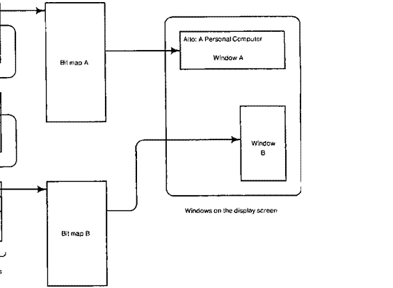
![]()
Alto: A Personal Computer Width = 32 LettMarg in Height = 150 Window A Bit map A 0 Width = 0 LeftMargin = 0 Height = 150 Window 0 Windows on the display screen Width = 15 LeftMargin = 17 Height = 300 Bit map B Display Control Blocks
![]()
B
(DCBs)
![]()
![]() Bit maps
Bit maps
Window A
Alto: A P
![]()
|
|
|
Bit map A |
||
|
|
00000100000000000000000000000000000000000000000000000... |
|||
|
|
|
A + 32 |
||
|
01100100100000000000000110000011100000000000000000000... |
||||
|
|
||||
|
A + 64 |
10010101110011000100001001000010010011001100011001100... |
|||
|
|
|
|||
|
A+96 |
10010100100100100100001001000010010100101010100010010... |
|||
|
Width= 32 |
||||
|
|
A + 128 |
11110100100100100000001111000011100111101000010010010... |
||
|
LeftMarg = 0 |
|
A + 160 |
10010100100100100100001001000010000100001000001010010... |
|
|
Height = 150 |
|
A + 192 |
10010100010011000100001001000010000011101000110001100... |
|
|
|
|
A + 224 |
00000000000000000000000000000000000000000000000000000... |
|
3.3 Composing the image
Because
many bits are needed to display an image, we have found the machine's ordinary
data manipulation instructions inadequate for
handling images. It is important to have fast ways of building up the most common kinds of images and
making certain common changes (e.g., moving or scrolling a window). For this purpose the Alto has one major
microcoded operation called BitBlt (for
bit boundary block transfer), with a surprising number of uses. It works on rectangles within bitmaps; such a
rectangle is defined by the width of the bitmap (which determines the spacing
in storage of vertically
adjacent elements), the address of the bit which corresponds to the upper left corner of the rectangle, and the height and width
of the rectangle (in bits). BitBlt takes two such rectangles. called the source and
the destination, and does
destination 4- F
(destination, source)
where F (ch s) can be s (move), d OR s (paint), d XOR s
(invert) or d AND s (erase), or any of these with s complemented. It is also
possible to supply a 16x4 rectangle for the source and have it used repetitively; this is useful for producing uniform
textures. The properties of BitBlt, which was designed by Dan Ingalls, are discussed in more detail in
[Newman-Sproull], where it goes under the name RasterOp.
BitBlt has a large number
of applications, among them
Painting
characters from a font, which is simply another bitmap, held somewhere in
storage, that contains
images of the characters. It is interesting to note that "characters"
can also be used to represent various
specialized kinds of graphics, such as the symbols in hardware logic drawings.
Drawing horizontal and
vertical lines (which are just narrow rectangles). Filling in rectangular areas
with textured patterns.
Scrolling an image across a
fixed rectangular window on the screen, or moving such a window around on the screen.
Moving an image onto the
screen from a copy elsewhere in storage.
Saving part of the image in
memory that is not part of the display bitmap. Later, the saved image can be copied back to cause it to
reappear on the screen.
The
Alto also has a specialized operation for painting characters; it is
considerably less flexible than
BitBlt, but easier to invoke and more efficient.
Sometimes
one would also like fast operations for painting arbitrary lines and curves,
and for filling solid areas bounded
by such shapes, but so far we have not found the need for these to be great. Instead, these requirements are
adequately met by the Alto's ordinary memory reference instructions, which can
be used to randomly access and update the display with complete flexibility. We have found this to be quite important, and believe that it is a
significant advantage of the Alto architecture
over conventional frame-buffer organizations. The ability to reuse part or all
of the bitmap memory for other
purposes when a full-screen display is not required has also been very important;
with the decreasing cost of memory this is no longer such a significant
consideration.
![]() 3.4.
Display hardware
3.4.
Display hardware
This display is supported by three microcode tasks and some very simple
hardware (Figure 9). Serial
video data is clocked by a 50 ns bit clock: everything else is clocked by the
machine's 170 ns main
clock, which is chosen to be an inteeral submultiple (224) of the display's
line rate (875*30= 26.25
kHz). A 16 word RAM and a
one word register implement a FIFO buffer
and synchronizer between the
processor bus and the shift register which serializes data for the display. There is a sync generator with a counter and PROM for horizontal sync and one for vertical sync, and logic to wake up the data task whenever the FIFO is
not full, the line task when horizontal blanking starts, and the field task when vertical blanking starts. There is also some logic to support the cursor described in section 3.5.
Processor
Bus
![]()
![]() FIFO
FIFO
|
Buffer |
|
Cursor SR |
|
||||||
|
|
|
|
|
|
|
||||
|
|
|
|
|
|
|
||||
|
Shift Reg |
|
|
|
Mixer |
|
|
Video to Display |
||
|
|
|
|
|
|
|||||
|
|
|
|
|
|
|
|
|
||
|
|
Control |
|
Wakeup |
|
|
|
||||
|
F2 |
Sync, Wakeup Request |
|||
|
Signals |
Request |
|||
|
|
|
Logic |
|
Control Block Format:
|
Pointer
to next control block or zero if last I - • |
|
|
8 R registers 74 Microinstructions 55 MSI TTL ICs |
|
|
I Left
Margin I I I |
I I Width |
I |
I |
|
|
Bitmap memory address |
|
|
||
|
Height |
|
|
||
The field task runs 60 times a second, and is responsible for
initializing the line task at the head of the chain of control blocks. It also generates a 60 Hz
interrupt. The line task runs every 38 p.s; it initializes the left margin width, bitmap address and bitmap
width for the data task, and advances to the next control block if the current
one is exhausted. When no control blocks remain, it goes to sleep until
reawakened by the field task. The data task outputs zeros until the left margin
is exhausted, then fetches
doublewords from storage and delivers them to the FIFO until the bitmap width is exhausted, after which it goes to sleep until
reawakened by the line task. A doubleword fetch takes six cycles or 1.05 s, and the 32 bits are consumed in 1.6
ps, so the data task consumes two thirds of the machine while data is being
displayed (which is 73% of the time, the rest being spent in retracing).
3.5 Pointing
A user working interactively with images frequently points at parts of
the image, to identify the spot
where something should be done, to select a menu item, to indicate the corners
of a region, etc. For this
purpose the Alto has a device called a mouse, which
fits comfortably under a hand and can be rolled
around on the work surface [English et al]. The mouse is supported on three ball bearings, and the x and y rotations of one
of these bearings are sensed by the Alto. The hardware senses motion by ±-1
increments in each direction (one unit is
roughly 1/200 inch), and microcode running
in the timed task uses this information to update a pair of mouse coordinates in storage. Often it is also nice to be able to draw, and the mouse can do this too,
albeit somewhat clumsily. When drawing is important, a tablet is used, but this
device interferes so much with the keyboard that it is
not generally popular.
It
is essential to have visual feedback which indicates the mouse position, since
there is no direct visual or
tactile connection between the mouse position and anything in the image on the
screen. This feedback is provided by the cursor, which
is a special 16x16 bitmap stored at a fixed place in memory, together with x and y coordinates that control where it is displayed. The cursor has its own microcode task, which runs after the
display's line task and loads two hardware registers with the proper cursor
data for the current scan line, and the x coordinate at which
its first element should
be displayed. The hardware starts shifting out the data when the display
reaches the specified picture
element, and it is oRed with
the main display data. The connection
between the mouse and the cursor coordinates is established
entirely by software, which may, for example, restrict the cursor to some region of the screen, force it
to move on a grid to facilitate lining things up, or make it "snap"
onto sensitive points when it approaches close to them. Much use is made of the fact that the cursor image, though small
(about 1/4" square), is programmable. This turns out to be extremely valuable, because the user is
much more likely to be looking at the cursor than anywhere else on the screen. A remarkable variety
of shapes can be represented on those 256 bits, and
a great deal of important information easily and unintrusively conveyed.
Another important property of the mouse is the three buttons on its top
surface. These alloy, the user to specify a number of commands using the same hand with which
he is pointing, especially
when the meanings of the buttons are modified by shift keys on the keyboard, or
by taking account of the
duration or frequency of clicks. The current state of each button (up or down) appears as three bits in a special memory
location, so that the program is free to attach meaning
to any detail of the user's interaction with the buttons.
3.6 Keyboard
The Alto has a standard office typewriter keyboard, augmented with a
small number (8) of extra keys. The keyboard appears to the program as four
words of memory; each of the bits in these words reflects the current state of one key (up or down). This
allows any key to be used as a shift
key, and as with the mouse, it permits a variety of non-standard
interpretations of the keys to be programmed, ranging
from repeating keys to a digital electronic organ manual.
4. Local storage
The Alto has a reasonably powerful and very reliable disk file system.
This file system is implemented
on a 2.5 megabyte moving-head removable-media rigid disk drive with which every
Alto is equipped. All Alto
software can read and write disk files, which are the usual interface among Alto software subsystems.
The
disk controller consists of one board of special-purpose hardware, and a share
of the Alto micromachine. The
disk controller and the file system were designed together, so that the
functions of the controller
match the functions of the file system. Thus, certain file system functions are
performed entirely by the
disk controller to insure speed or reliability. These functions are easily implemented because the full power of the Alto processor is available
to the controller.
4.1 File
system
An Alto
disk pack contains a set of disk files. A disk file is a sequence of bytes,
identified by a serial
number unique within the disk pack. The disk controller and the file system
software together implement
a set of operations to create, extend, truncate, or delete files, and to read
or write sequences of bytes
within a file. A file is implemented as a non-contiguous sequence of fixed-length pages recorded on the disk pack. Each
page of a file except the last is completely full of data (Figure 10).


![]()
![]() Cyl, Hd, Sec
Cyl, Hd, Sec
File #
Page #
# bytes
NextDA PreviousDA
![]()
![]() k---,,,,--) n---y--..—) %. ,
k---,,,,--) n---y--..—) %. ,
-"Yr‑
Leader page of First
data page First data page
file RootDir of
Altol.txt of RootDir
![]()
![]()
-v‑
Last data page Second data page
of RootDir of
Alto .txt
The Alto file system is designed to be reliable. Many file systems have
the property that bad data on a single page may create such confusion that the
good data on the rest of the disk is practically useless. To control the global damage that could result from
localized errors, the Alto file
system distributes structural information to each page on the disk. Each page
contains a special record
called the label, different from the data record, that says, for
example, "I am now serving as page 17 of file number 34152." Page 0 of a file, the leader page, holds information about the file: its alphanumeric name, the date of last modification, and so on;
actual data begins in page 1. The distributed
structural information recorded in the label (serial number, page number,
length) and in the leader page (name) is the basic file system data
structure.
The
basic data structure is supplemented by a set of hints, performance-improving assertions whose truth can easily be verified. Because it is inefficient to scan the
entire disk to find the leader page
of a given file, a directory file maintains hints about file locations. If the
directory file says that page 0
of file number 3456 is located at disk address 7890, then before doing anything
irreversible at disk address
7890, the disk controller checks whether the label record at that address
admits to being page 0 of
file 3456. To allow rapid access to a sequence of pages, each label records as
hints the disk addresses of the
immediately preceding and following pages of the file (Figure 10). If hints of any sort are found to be erroneous, they can
be reconstructed from the distributed structural information. In fact, one of the most important programs
on the Alto is the hint-reconstructing Scavenger.
The disk controller makes it easy to use hints properly, and to do other
common file-system operations.
A disk operation is invoked with a command
block, a group of words
in main memory that specify a disk
address, a page buffer address in main memory, and the transfer operation to be
performed (Figure 11). The disk controller is
activated by putting the address of a command block into a particular main memory location. The
controller performs the requested operation, writes the final status in the command block, and (if all went
well) automatically proceeds to the next command block in a chain of blocks, linked by pointers. Disk command
blocks are designed to be included in more complex operating system data
structures describing pending disk transfers.
File
system damage results as often from errant software as from errant hardware.
The file system/disk controller design attempts to minimize damage in two ways.
First, each disk command block is required to contain the seal, a certain exact bit pattern. The disk controller will stop immediately if it encounters an improper seal.
Thus if the disk controller is accidentally activated on a block of memory that is not a legal disk
command block, its seal would probably be improper, and file system damage would be avoided.
The
second way to assure file system integrity is to check the label record before
reading or writing, as
mentioned earlier. Many disk controllers in other systems implement a header
record for each page,
separate from the data record, that is checked before reading or writing the
data record. This strategy
provides protection from failures of seeking or sector counting hardware, but
not from software failures.
An Alto disk sector incorporates separate header, label, and data records. The disk controller checks the header record to be sure the access
hardware works, and then checks the
label record to be sure that
the file system software works, before reading or writing a data record.
4.2 Disk interface
The disk controller consists of two micromachine tasks, four
R-registers, about 150 microinstructions, and 55 mst TTL ICS (Figure 11). The hardware is modest because it takes advantage of the computational power available
in the micromachine. The hardware does only what the micromachine cannot do, either because of performance
limitations or because remote sensing
or control is involved: cable driving and receiving, data buffering, data
serialization and de-serialization,
data encoding, sync pattern detection, and micromachine communication. With the
particular disk drive used
on the Alto (Diablo Model 31), the disk controller is responsible for encoding data into a self-clocking Manchester
code during a write operation, but during a read operation
the disk drive itself performs data-clock separation.
Various applications eventually led us to interface a much higher
performance disk (CalComp Trident)
as an option. The differences between the two disk controllers are almost
entirely in areas where the micromachine has sufficient performance to handle
some function for the slower disk, but not for the faster one. For example, although the Alto has sufficient
main memory bandwidth to handle
the Trident (9 Mbits/sec vs. 1.7 Mbits/sec for the Diablo), task wakeup latency
(the time from when a wakeup is requested to when the task gets control of the
micromachine) can be up to 2 Its, so multi-word
buffering hardware is required in the faster controller.
4.2.1 Disk sector task
One micromachine task, called the sector task, is invoked whenever a
sector notch on the rotating
disk pack passes a reference location on the disk drive, There are 12 such
notches around the
disk, and one of them passes the reference location every 3 ms. The sector task
can run at low priority because its needs for micromachine computation (about
12 p.․) can be satisfied at any time in a 100 its interval. When the sector task is invoked, it
records the final status of the just-completed
transfer operation (if there was one) in that operation's disk command block,
records any requested interrupts in NIW, and checks to see if another command block requires processing. If there is no work to do, the sector task goes to
sleep. This permits lower-priority tasks to run until another sector notch is encountered.
If there is new work, the sector task decides whether the
disk access machinery is positioned at the correct cylinder and sector. If the cylinder is incorrect, a seek
operation is initiated, using the controller hardware. If both sector and cylinder positions are correct,
the data transfer is enabled by
leaving the necessary state information in R-registers, and commanding the
controller to generate disk data task wakeup
requests. Finally, the sector task
sleeps.
![]()
![]() Shift Reg
Shift Reg
![]()
![]() Butler
Butler
![]()
![]()
![]() Butter
Butter
Command
Control
----)11°- to Disk
Phase Encode
![]()
![]()
![]()
![]()
![]()
![]()

![]()
![]()
![]()
![]()
![]()
![]()
![]()
![]()
![]() St tt_g__is from Disk
St tt_g__is from Disk
![]()
![]()
![]()
![]()
![]() CTASK F210:31
CTASK F210:31
|
|

![]()
![]() HWakeup
HWakeup
Request
Control Block Format:


![]() 4 R registers
4 R registers
144
Microinstructions 55 MSI
TTL ICs
4.2.2 Disk data task
The other task, called the disk data task, is invoked at a very high
priority during reading (or writing) whenever the one-word data buffer in the controller needs
emptying (or filling, respectively). This task is
awakened about every 10 As, and transfers a single word in at most 1.7
(unlike the display task, which transfers two words per wakeup in 1 Ills). Thus during disk transfers up to 20%
of the micromachine's time is devoted to servicing the disk controller.
The
disk data task is expected to read, check, or write each of three records in a
sector: the header, the label, and the data. Each
record consists of a preamble area written as all 0 bits, a synchronization
pattern consisting of a single 1 bit, a number of information words, and a
checksum word. The preamble and
synchronization bits allow a tolerance for mechanical and electrical misalignment
between writing and reading.
In
a typical operation the data task might check the header and label records of a
sector, and then write its data record. To read or
check a record, the Alto waits until the disk head is over the preamble to that record, then reads until the sync
pattern is recognized, then gets words from the disk and writes them into memory or compares them with words fetched from
main memory, and finally compares the
computed checksum against the one read from the disk. To write a record, it
must write a certain amount of preamble, then a sync pattern, then the data
fetched from main memory, and finally the computed checksum.
A small piece of actual microcode for the disk data task
will make the preceding description concrete. In the microassembly language below, all the clauses between a
pair of semicolons (; xxx F
yyy, zzz, ;)
assemble into one microinstruction (see Figure 5). For example, in the first line,
InPreambleWait:
L MinusPreambleRemaining+1,
Block;
MinusPreambleRemaining is an R register (say, 16), so RSEL = MinusPreambleRemaining (16), ALUF = BUS+ 1
(5), BS = (0), Fl = BLOCK [task specific] (3), F2 = NULL (0),
LL = Yes (1),
LT = No (0). and the NEXT field
is assigned by the microassembler to point to the next microinstruction in sequence. The label InPreambleWait is defined to be the microinstruction address
chosen for this microinstruction by the microassembler.
One further general point is that conditional
jumps and dispatches are implemented by oRing a computed value (usually just 0 or 1, but not always) with
the NEXT address being fetched as part of the next microinstruction. Conditional clauses are identified by a trailing
?. For example,
...,L<O?
...,GoTo[0:PreambleDone, 1:InPreambleWait] •
The
L<O? clause in the first microinstruction will cause a 1 to be ORed with the
NEXT field of the next microinstruction, if and only if the previous value of the L
register is negative. The second microinstruction
includes a NEXT field
pointing to Preambl eDone, and in addition it tells the
assembler to locate PreambleDone at an even address and InP reambl eWait at the next
successive odd address, so
that PreambleDone OR 1 = InPreambleWait.
The microcode fragment
given below uses several functions to communicate with the hardware interface. All of
them are task-specific.
Block (Ft) tells the controller hardware that the
microcode task has run, and the wakeup request should be removed.
Di skBuf f erWord*- (Fl) loads the one-word output buffer in the
disk controller hardware from
the bus.
4-DataBuf ferWord (Bs)
puts the contents of the one-word input buffer in the disk controller onto the bus.
Di skCommandRegister+- (Fl)
loads the command register in the controller from the bus. The bits in that register then fan out to control
several independent conditions in the controller hardware. One bit (Use ReadCloc k) determines
whether the controller bit clock is being generated from a crystal oscillator in the controller, or
whether it is inferred from the
data being read from the disk. Another bit (WaitForSyncPattern) determines whether
the controller should suspend wakeup requests until the arrival of the sync
pattern from the disk.
ReadWriteOrCheck? (F2) causes a 2-bit dispatch based on whether the
record is to be read,
written, or checked (compared with memory data). The two bits have earlier been
placed by the microcode into a special register
in the disk controller.
The code begins with a
description of the R registers used:
The code uses four R
registers, although for clarity five names are used: MinusPreambleRemain ing: a negative count of the number of words of preamble remaining.
RecordWordCount: the
number of words in the record being read or written (e.g., the data record is 256 words long).
BufferBottom: the address of the first word in main memory of the buffer for this
record.
OneBeyondNextBufferWord: a
pointer into the main memory buffer where the next word should be placed. The pointer is always
"one beyond" where the actual store will be done.
Checksum: a
register to accumulate the exclusive OR of all data words read or written in
the record.
As we join the story, the data task has begun
"spacing" into a disk record in preparation for reading, writing, or checking it. If reading or checking, this means
marking time until good data is known to be under the read
head. If writing, this means writing preamble.
In this loop the microcode counts through the
preamble, one count per data task wakeup. Although no data is being transferred, the disk controller is waking up the
data task each time the 16-bit buffer is full, so that it
can count preamble bits. Between wakeups, the data task's micro-program counter
rests pointing at either InPreambleWait or PreambleDone.
InPreambleWait:
L MinusPreambleRemaining+l,
Block;
MinusPreambleRemaining 4- L,
L<O?, Task;
DiskBufferWord t PreambleConstant,
GoTo[0: PreambleDone, 1:InPreambleWait]; Send more preamble if writing.
Now
the preamble waiting is over. If reading, this means that the head is known to
be over a good preamble area
before the sync pattern. If writing, this means we should now
write a sync pattern.
PreambleDone:
T F RecordWordCount;
L 4- BufferBottom+T, ReadWriteOrCheck?;
OneBeyondNextBufferWord
4- L, Block, Set
up pointer into buffer.
GoTo[O:SetupRead, 1:SetupWrite, 2:SetupCheck];
SetupCheck:
Adjust by 1 to make transfer
loop exit test more efficient
L 4- BufferBottom-1;
BufferBottom F L;
SetupRead:
DiskCommandRegister 4- UseReadClockAndWaitForSyncPattern,
GoTo[SetupChecksum];
SetupWrite:
DataBufferWord 4- SyncPatternConstant:
SetupChecksum:
L
4- Start ingChecksumConstant, Task; Initialize
Checksum register.
ModifyChecksum:
Checksum 4- L;
The data task's micro program counter rests here
between transferring words. If we are reading, and if this is the first word of
the record, then the data task will wait here until a word has been read
following the deserializer's recognition of
a sync pattern. Note that the transfer loop transfers data from high to low
addresses; this simplifies the exit test
TransferLoop:
MAR 4- L 4- T 4- OneBeyondNextBufferWord-1;
Start
main memory interface by supplying address to MAR.
OneBeyondNextBufferWord
F L,
ReadWriteOrCheck?:
L 4- BufferBottom–T, Compute number of words remaining
to transfer.
GoTo[O:ReadLoop, 1:WriteLoop,
2:CheckLoop]; Dispatch.
ReadLoop:
T Checksum, Block, L=0?; Check L: Enough words
transferred?
L 4- (MD 4- DataBufferWord) XOR T. Task,
GoTo[0:ModifyChecksum, 1:TransferFinished];
![]()
![Text Box: Task, GoTo[0:ModifyChecksum, 1:TransferFinished]:](25-AltoOCR_files/image181.gif) modify checksum.
modify checksum.
•
TransferFinished:
Checksum 4- L;
The task's program counter rests here after
sending the last data word to the controller, or reading the last data word from the controller. Now we must either send the
computed checksum to the controller or compare the computed checksum
with that read from the controller.
T 4- DataBufferWord 4- Checksum,
ReadWriteOrCheck?; Only
writes into outgoing buffer word.
L 4- DataBufferWord-T, Block,
GoTo[O:CheckChecksum, 1:FinishRecord,
2:CheckChecksum]: This
uses the incoming buffer word.
Now if we were reading or checking. we test for correct
checksum by checking whether L is 0. etc.
In the main reading loop, all but one of the microinstructions are
executed concurrently with the
main memory transfer (i.e., between MAR- and MD., which are as close together as they can be). This is usually true as well for other
high-bandwidth controller microcode loops in the machine. Thus the main speed bottleneck in the Alto is
shared access to a single memory interface. The additional degradation resulting from also sharing a
single processor is minimal because so much processing
is overlapped with memory references.
ReadWriteOrCheck? is a good example of trading off controller hardware against shared
processor time, register space, and microcode space. Obviously the same effect
could have been obtained
by dispatching on the value in an R register in the
micromachine, or by having completely separate micromachine routines for reading, writing, and checking.
Usually the decision was made to
minimize controller hardware. But in this case by introducing a small amount of
extra hardware (about two la) in the controller, one R-register or about 30
microinstructions were saved. It. was economical
in 1973, but might not be today.
5. Communication
A personal computer provides substantial, predictable service to a single
user. Much of the service he wants, however, cannot be provided by his machine
alone, either because sharing is essential
to the service or because of cost. Communication with other computers and other
users is therefore needed. The communication
system expands the service available to an individual, by allowing
several users to share resources.
Such
sharing is advantageous for two reasons. First, it allows several users to
access the same data.
For example, a person who composes a memorandum using text-editing facilities
contained entirely in his
Alto, may wish to distribute copies to several other people. He transmits the
data representing the memorandum
to the Altos of the recipients; each of the recipients can then read it on his
Alto display. This use of communication is analogous to the use of the
telephone or U.S. mail.
Communication can also be used to share resources for economic reasons.
Although it is too costly to provide a
hard-copy raster-scan printer for each Alto, a group of users may share a
printer, transmitting to the printer the data
and control information necessary to print a document. Sharing is also
economical for high-capacity file storage or for special-purpose processors too
expensive to replicate for each person.
At the time the Alto
was designed, several computer communication networks such as the ARPA network [Kahn] had
demonstrated the value of packet-switched networks for sharing resources and providing personal communication among research
collaborators. A design suited for personal computers. however, has objectives rather different from those of a
remote computer network such as the ARPA net:
The
transmission speed should be high enough that most users will not
notice the presence of the
network. If network bandwidth approximately matches local disk bandwidth, the user may not know or care whether a file is
retrieved from a local disk or from a remote disk.
The size of a network linking personal computers must not be limited. It is not unreasonable to imagine networks linking
thousands of personal computers. At the same time,
just two of three computers can constitute a reasonable network.
The reliability of the network is extremely important when essential
services such as printing depend on
communication. If a user's personal computer malfunctions, he can take his disk
cartridge to another one, but a network
malfunction severs his access to essential services. In addition. many users
are inconvenienced when the network fails, but only one when a machine
fails.
Personal computers tend to
be near to each other and to the services they need, thus permitting a local network transmission technique for clusters of machines.
A design for a communication system must anticipate the need for standard communication protocols in addition to standards for the physical transmission media. The
protocols control the flow,
routing, and interpretation of data in the network. Just as the design of the
Alto disk controller addresses the needs of a
file system, so must the design of a network address the needs of communications protocols. However, the Alto was
designed at a time when experience with protocols was limited: many lessons had been learned from the ARPA protocols, but newer designs such as Pup [Boggs et all and TCP [Cerf-Kahn] had yet
to emerge. The Alto therefore provides a general
packet transport system, which has been used for a number of protocol
experiments and evolutionary designs.
5.1 The Ethernet local network
The
Ethernet communication system [Metcalfe-Boggs] is the principal means of
communication between an Alto and other
computers. An Ethernet is a broadcast, packet-switched, digital network that can connect up to 256 computers, separated by
as much as a kilometer, with a 3 Mbit/sec channel. Control of the Ether is distributed among the communicating
computers to eliminate the reliability
problems of an active central controller, and to reduce the fixed costs which
can make small centralized networks uneconomical.
A
standard Alto includes an Ethernet controller and transceiver. As soon as there
are two Altos within a kilometer of
each other, connecting the transceivers together with a coaxial cable establishes an Ethernet. Additional Altos and
other computers can be connected simply by tapping into the cable as it passes by, above a false
ceiling or beneath a raised floor. Connections can be made and power turned on and off without disturbing network
communication.
An Ethernet is an efficient
low-level packet transport mechanism which gives its best efforts to delivering packets, but it is not error free. Even
when transmitted without an error detected by the sender, a packet may not reach its destination
without error; thus, packets are delivered only with high probability. A hierarchy of layered
communication protocols is used to achieve reliable transmission on the
Ethernet, by requiring receiving processes to acknowledge receipt of correct packets
and sending processes to retransmit packets whose correct receipt is not
acknowledged.
5.2 The internetwork
Although the physical size and addressing of the Ethernet are limited,
many local networks may be
connected together into an internetwork.
The internetwork is
implemented by building gateway computers (usually Altos) that connect two or
more networks, often using long-haul digital communication
to connect with gateways on distant local networks. The gateway is responsible
for routing packets in the internetwork: it
receives a packet from a local network, interprets a destination address in the packet, and then
transmits the packet into another network which will get it closer to
its ultimate destination. Sometimes packets are forwarded through several
gateways
before they arrive at the
proper local network. As of summer 1979, the Xerox internet provides service to several hundred computers on 25
networks interconnected by 20 gateways.
5.3 Implementation
The Alto Ethernet controller (Figure 12) contains about 75 MSI TTL ICs— it is slightly larger than
the disk and display controllers. The transceiver, on the other hand, is much
smaller and less expensive
than either the disk drive or the display monitor. The controller hardware
consists of the following
functions: phase decoder, receiver shift register, FIFO buffer and synchronizing register, transmitter shift register, phase encoder, and micromachine interface.
The FIFO buffer is shared by the transmitter and receiver, so the interface is
half-duplex: it can either be transmitting or receiving but not both simultaneously. This is not a severe
limitation, since the Ether itself is half-duplex. It does make hardware checkout more difficult,
however, because the controller cannot be looped back on itself; also, the software must make a special
check for packets that it sends to itself. Up to three Ethernet interfaces can be attached to an Alto.
Unfortunately the tasks cannot share a single copy
of the microcode, since the micromachine cannot make indexed R-register
references.
The
microcode uses one medium-priority task, two R-registers, and about 100
microinstructions. The task consumes 16% of
the machine in the data transfer loops, since it runs for five cycles (one memory reference) every 5.44 tis (one
Ethernet word time), doing all of its bookkeeping while waiting for the memory. To reject a packet the
address filter requires 13 cycles (2.21 iis), which consumes as much as 20% of the machine in the
improbable case of minimum length (2 word) back-to-back packets. The rest of the microcode is executed once per
packet accepted or transmitted, and so consumes a negligible number of
cycles.
The
Ethernet task communicates with a program much as the disk and display tasks
do. The program builds a command
block describing the operation to be done. When the Ethernet task wakes up, it carries out the operation, and then
posts status in the command block and causes an interrupt by ORing a word from the
command block into NIW. The disk and display have periodically occurring events (sector notches and
scan line retrace) which cause their tasks to wake up and check for commands from the software, but
there is no such periodic event for an Ethernet. Instead,
there is an S-group instruction which the program executes to set a flip flop
in the Ethernet hardware: this flip flop wakes up the Ethernet task to act on
the command block. Disk and display commands
complete after a finite time, but an Ethernet receiver can be started and not
receive a packet for days. Hence
programs always use interrupts to recognize completion of an operation, rather than busy-waiting as many disk drivers do.
Finally, Ethernet command blocks are not chained, partly because of a shortage of microcode space in the early
implementations, and partly because it was not then clear how to make
use of chaining.

![]()
![]()
![]()

![]()
![]()


![]()
![]()
![]()
![]()
![]()
![]()
![]()
![]()
![]()
![]()
![]()
![]()
![]()
![]()
![]()
![]()
![]() Phase
Phase
Encode
Data to
![]()
![]()
![]() Transceiver
Transceiver
|
CTASK |
|
|
Dispatch Logic |
Next |
||
|
F210:31 |
Address Wakeup |
|||||
|
F1[0:31 |
|
|
Control |
|||
|
|
||||||
|
Function Decode |
Wakeup Request Logic |
|||||
|
Signals |
Request |
|||||
|
|
||||||
Control
Block Formal:


![]()
![]() 2 R
registers
2 R
registers
95 Microinstructions 75 MSI TTL ICs
Packet address filtering is done by the microcode. When the hardware has
accumulated the first
word of a packet, it wakes up the microcode to check the destination address
byte. The microcode accepts the packet and copies
it into memory if any of the following conditions is met:
· the destination address in the packet matches the
host address field in the command block:
· the destination address is zero (in this case the
packet is a broadcast packet, and is received by all machines);
· the host address is zero (in this case the
machine is said to be promiscuous,
and receives all packets).
Otherwise the microcode
tells the hardware to ignore the rest of the current packet, and go to sleep until the beginning of the next packet. The
address filter takes about 20 microinstructions; done in hardware it would take about 8 ics.
The flexibility afforded by this filtering scheme has many applications.
Any machine can substitute for another by
using the other machine's address in the host address field. Promiscuity is invaluable for debugging protocols, since a
machine can peek at all of the packets flowing between two others. It is also easy to study the
performance of the net by monitoring all the traffic. Broadcasts are used to locate resources and to
distribute globally useful information. A less desirable consequence is that the Ethernet itself provides no security;
applications which need secure communication must use encryption.
The
choice of an eight bit address has proved to be unfortunate, since it means
that a machine cannot
have a unique hard-wired serial number which is normally used as its host
address. Instead, each Alto has a station address specified by jumpers on the
backplane, which is unique only among the
machines on the particular Ethernets it happens to be on.
Two
or more Ethernet transmitters collide
when they simultaneously
decide that the Ether is free and begin
transmitting. When a transmitter detects collision, it aborts transmission and
waits a random time interval before trying
again, so as not to collide repeatedly. As the load on the net increases, a transmitter retries less vigorously,
by doubling the mean of its random interval each time it participates in a
collision. This exponential
backoff algorithm is done
by the microcode and a small
amount of hardware. The software zeroes the LOAD location in the
Ethernet command block each time it issues
an output command, and the microcode shifts a one bit into it each time a
collision happens. The microcode generates a random retransmission interval by
masking the LOAD location with the real time clock R-register maintained by
the timed task, and then waiting for that interval by telling the hardware to wake it up each time the timed task
wakes up, and decrementing the
interval register at each wakeup. When the register goes to zero, the microcode
again tries to transmit. After 16 consecutive collisions the LOAD location overflows, and the microcode gives up and posts a failure code
in the command block. This algorithm takes about 20 microinstructions; done in hardware it would require about 10 ICs.
6. A controller for a raster-scanned printer
The Alto is
predominantly a versatile 1/0 controller: the design emphasizes the needs of
high-bandwidth iio for personal computing,
and relegates instruction interpretation to secondary importance. One of the objectives of the design is
to provide a convenient framework in which to build experimental or
special-purpose uo controllers, in addition to those for the standard display, keyboard, mouse, disk, and Ethernet. This section
illustrates how the resources of the Alto are harnessed to a complex task: an
interface to a high-speed raster-scanned page printer. The design shows
how the page-generation algorithm is first analyzed, and then divided into
parts that are implemented in software, microcode, and hardware.
The
objectives of a printer are very similar to those of the Alto display: several
thousand characters may
appear in arbitrary sizes, rotations, font styles, and positions on the page;
text may be proportionally
spaced; characters may overlap one another (e.g., overstrikes); non-text
imagery such as lines and curves may appear. Printing quality generally exceeds
that of a display by using higher resolution—a typical device might print in
one second an 8.5 by 11 inch page defined with 350
dots/inch (roughly 4000 horizontal scan lines of 3000 dots each).
These
observations suggest that the same techniques used to generate a digital video
signal for the Alto display be used to drive a printer. The modest average data
rate of 12 Mbits/sec means that
an image of the page could be buffered in Alto memory and read out to generate
video, using the same sort of controller as the Alto display. The image of the
printed page can be created the same way as that for a display: using a character table that gives the x and y position and
character code for each character that appears in
the image. and a font table that
defines a rectangular bitmap pattern for each character, BitBlt is used to OR each character's pattern into the
bitmap buffer at the proper coordinate
position. Unfortunately, this simple approach fails for two reasons: the Alto
does not have enough memory to buffer
a full page image (12 million bits), and the processor cannot execute BitBlt fast enough to generate a bitmap
for a moderately complex page in one second. These two problems force changes
in the image-generation algorithm. After describing the new algorithm,
we sketch its Alto implementation.
Because
buffering the entire page is impractical, an incremental algorithm must be used to generate portions of the image in sequence, using a
smaller buffer. The image is divided into bands of 16
scan lines each, and the entire page image is generated by creating the image
for each band in turn.
This scheme requires two buffers, each capable of holding the bitmap for a
single band: while one buffer is
being converted into a video signal and sent to the printer, the image of the next band is being prepared in the other buffer.
The
incremental approach requires modifications to the image-generation algorithm
described for a full-page
buffer. The problem is to identify those characters that lie wholly or partly
in the band being generated.
Although the entire character table can be scanned to compute, for each entry, whether the character lies in the band, it
is more efficient to sort the table by the band number
in which the character begins (i.e., by y coordinate
of the topmost scan line). The sorted
table allows easy
identification of "new characters," those that start within the band
being generated.
Breaking
the page image into bands inevitably causes some characters to span two or more
bands, either because they
are more than 16 scan lines high, or because their image on the page happens to cross a band boundary. For these
characters, the image-generation process is not completed when a band is generated;
instead. a portion of the character is left over and
must be continued in the succeeding
band (Figure 13). The image-generation algorithm records left-over characters in a list that contains sufficient
information to continue image generation (BitB10 in the next band. The companion data structures for new
and left-over characters are characteristic of many incremental image-generation algorithms, such as
those for solid polygons and hidden-surface images
[Newman-Sproull]. The algorithm to generate the image of a band is:
1) Clear the band buffer to zero.
2) For each character in the character table for this band:
2a)
Use the character code
extracted from the character table to enter the font table and find a character bitmap, together with a width and
height.
2b)
OR into the band buffer the image of the character, at the
specified position.
2c) If the
character's image does not terminate in this band, save a left-over entry, specifying the x position of the character, its width, its
height (now reduced), and a pointer to the
beginning of the next scan line of character bitmap information in the
font table.
3) For each character in the
left-over table formed when generating the previous band:
3b) Same as step 2b.
3c) Same as step 2c.
4) The image in the band buffer is now ready to
be converted into a video signal and sent to the
printer.
The algorithm was analyzed carefully to design an implementation for the
Alto. Table 1 gives several
properties required of the memories used in the algorithm, obtained by software
simulations of the printing of typical pages. These simulations lead to a
number of design decisions for the algorithm and controller. Consider the size of a band: 16 scan lines. The
greater the number of scan lines in a band, the larger the band buffers, and
hence the expense. The smaller the number of scan lines, the more frequently the left-over tables must be read and
written while generating a page.
The table shows that a band size of 16 scan lines yields both modest left-over
bandwidths and inexpensive
band buffers. It also shows that the memories required divide into two classes:
small and fast (band
buffers) and large but slow (font, character and left-over tables). This division
leads to an implementation
strategy for the Alto: the main memory will hold the font, character, and left-over tables, and the controller will
hold the band buffers, together with some image-generation aids. Such a division is feasible only because
the Alto micromachine can intimately control the image-generation hardware, using character parameters and
pattern information read from main memory.
![]()


![]()
|
·
• • I • n I ' • • ' |
|
|
1 0 0 I I 12 0 0
0 0 : 1 0
0 0 0 0 |
|
![]()
![]() Figure 13. Schematic diagram of the
image-generation process for printing a page. The band buffers show a character that does not
completely fit in band L It has a "left over" part extending into the next band.
Figure 13. Schematic diagram of the
image-generation process for printing a page. The band buffers show a character that does not
completely fit in band L It has a "left over" part extending into the next band.
Band buffers
Clear buffer
Generate
image
Output
video Font table
Character table Left-over list
Table I
Size (bits*103)
Bandwidth (bits*106/page)
30
12,3 6+
12.3
368+ 2.4+
80+ .08+
6.4+ .5+
Numbers ending in
"+" increase roughly linearly with page complexity.
6.1 Implementation
The organization of the printer controller is shown in Figure 14, It is
logically divided into two parts that operate concurrently, the video generator and the image
generator. The
video generator reads
data from one of the two band buffers, converts it into a video signal. and
transmits the signal to the
printer. As each 16-bit word is read from the buffer, zeroes are written back
to clear the buffer for subsequent image-generation.
When the video generator has emptied a buffer, it switches buffers and begins
emptying the other one.
The
image generator portion of the controller composes the image in the buffer that
is not being sent to the printer, under control of microcode in the printing task. The micromachine sets several parameter registers that describe the dimensions and position of
a character to be added to the band buffer (width, height, x, and
y), Then it enters a tight loop, reading the
character's bitmap pattern
from the font table, and passing two 16-bit words to the controller every
microsecond. This pattern
passes through a FIFO and is shifted to align it with the word
boundaries of the band buffer. After
masking to account for the ends of a character, these 16 values are used to
enable writing new data
values into selected bits of a particular band buffer word. An "ink"
memory provides the data to be
written at these positions. Thus the character pattern, shifter and mask
determine where a character appears in the band, while the ink memory determines the video data values, and thus allows characters to appear
to have texture or halftone patterns. When the interface signals to the processor that it is finished processing the
current character, the microcode reads the controller status, including the height register, to
determine whether the character was completed, or whether a left-over entry must be made, and records the
left-over entry in Alto memory if necessary. The microcode repeats this process
for all the characters that appear in the band. When the image for the band is completed, the printing task sleeps
until the video generator switches buffers, indicating that the task
must begin generating the image of the next band.

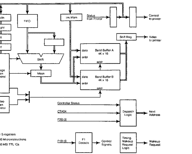
![]()

![]()
![]()
![]()
![]()
![]()
![]()
![]()
![]()
![]()
![]()
![]()
![]()
![]()
![]()
![]()
![]()
![]()
![]()
![]()
![]()
![]()
![]()
![]() Figure
14. The printer controller.
Figure
14. The printer controller.
The design of the printer controller is extremely economical, because it
takes maximum advantage of the
facilities already available in the standard Alto: substantial memory and a
versatile micromachine. This
approach retains the flexibility to change easily the sizes, formats, and
contents of important
structures: the font and character tables. The special hardware helps implement
a general mechanism for composing page images (BitBlt), a mechanism that places
no restrictions on the size, position, or
content of characters, nor on the number of different character shapes that can
appear on a page. Indeed, the controller
will generate arbitrary video patterns. including lines, curves, and halftones. The performance of the
system is limited by two constraints: (1) the font and character tables must not exceed the size of
Alto main memory; and (2) the time available to generate a band dictates the number of micromachine cycles available to
read character patterns from memory and pass them to the controller.
Each of several dozen printers in the Xerox research environment is
driven by a printer controller,
plugged into a standard Alto. Although the page-printing task is
complex, the special hardware
is not large (about 300 ics) because of extensive use of microcode and memory
resources in the standard Alto. The design
illustrates how a page-generation algorithm was analyzed and then implemented using appropriate facilities:
macroinstruction programs for y sorting. microcode
for left-over table management and font table
references. and special hardware for the "inner loops" of image and
video generation.
7. Applications
A successful personal computing environment depends not only on
economical hardware and devices for communicating with humans, but also on
software constructed to meet personal computing needs. This section surveys the major software systems that have
been built, and discusses the impact of the
local network on the Alto computing environment.
7.1 Programming environments
Two kinds of programming environments have developed on the Alto:
conventional compiler-based
systems, and fully interactive environments. The first conventional environment
to be constructed is implemented
almost exclusively in the BCPL programming language, and includes common tools: a compiler, an assembler, a linker,
a debugger, an "open" operating system [Lampson-Sproull], a command processor, file-manipulation
utilities, etc. Subsequently, the Mesa programming language was designed and implemented on the Alto [Geschke et al] [Mitchell et al]. Both of these environments have been used extensively to build
applications.
Interactive
programming environments emerged to take advantage of the personal nature of
the Alto. The Smalltalk
environment turned the Alto into an "interim Dynabook," a prototype
for a personal dynamic medium that emphasizes visual
and audio communication [Kay-Goldberg] [Kay77] [Kay78] [Ingalls]. Smalltalk has been used to interact with documents
containing text and graphics, to build
visual animations [Baecker], to synthesize music. and to build a variety of
simulations of personal interest.
An
implementation of Interlisp [Teitelman78] explored the problem of providing a
large interactive environment on the Alto [Deutsch]. Although the Alto
micromachine was successfully adapted
to interpret byte-coded Interlisp instructions at reasonably high speeds, the
small main memory of most Altos at the time (64K)
proved to be a crippling performance limitation.
The
various programming environments used on the Alto coexist gracefully by sharing
only files stored on the local
disk, and network protocols for communication among computers. No other facilities of the Alto are standardized.
This policy allows each environment and each application to exploit the
hardware in novel ways; for example, it fosters different strategies for using the display and interacting with the user.
It also allows a language or application to use special-purpose
microcode to interpret instructions or perform application-specific
calculations. The policy has a few
drawbacks: failure to standardize the use of the display, for example, makes it
essentially impossible for one Alto to be used as a remote terminal to
another one.
7.2 Personal applications
Some
applications use the Alto as a stand-alone computer, usually making extensive
use of the display, mouse and
keyboard for interaction. The most commonly used applications of the Alto
today
are the various programs developed for document production: a text editor that
supports a wide range of formatting styles and
text fonts, and a set of "illustrators" to prepare diagrams using
geometrical figures such as lines, circles, and curves. or raster images
obtained by scanning existing documents or by
free-hand drawing. Many of the display techniques used are described in [Newman-Sproull]:
camera-ready copy for that book was produced with Alto document-production
software.
Some uses of the Alto support research in computer science within Xerox.
The best example is a
design automation system used to aid designers of digital hardware. Logic
drawings are prepared with an
illustrator, and are then analyzed by a program to determine what integrated
circuits are pictured in the
diagram and how they are connected. Other software then checks loading rules,
makes wire lists, and drives semi-automatic wiring equipment.. The Alto also
serves as a console computer
to simplify debugging or diagnosis of experimental hardware. An umbilical cord
connects the Alto to the
hardware so that it can load registers and memories, issue control commands
such as "single step,"
and read back important internal state. An Alto program presents this
information on the
display, accompanied by symbolic names of the registers or signals in the
experimental hardware. The
display also presents menus of operations, such as "step," that are
invoked by pointing with the
mouse and cursor. In this way, the Alto is used to provide a comfortable user interface for an engineer, technician or system programmer working on
the hardware.
7.3 Communication in applications
No
Alto users depend only on the resources available within a single Alto: all use
communication to extend
these services. Even the user of document-production application requires communication to obtain hardcopy output at a
shared printer or to distribute a document file to other users. Alto applications and users depend on a wide variety of
services implemented on server machines throughout
the network:
·
Printing. An application program running in any Alto may
transmit to the printing server a description of a document to be printed. The
printing server is an Alto that queues requests,
and later prints the files using the raster printer controller
described in Section 6.
·
File
storage. File services are
provided both to allow sharing of files among users and to escape the limitations of the local storage
available on the standard Alto. The service machines have one or more high-performance disks attached, and offer
several different styles
of file access. Some provide a "page level" access [Swinehan et al], some a "file transfer"
access patterned after the ARPA
network file transfer
facilities [Crocker et al], and some a "transaction access"
suitable for implementing a file service that is distributed over several machines [Lampson-Sturgis] [Israel et al].
·
Afailboxes.
A popular application of the
Alto is an electronic mail service. The personal machine is used to prepare messages for transmission to
other Alto users, and to display and retain
on the disk messages that have been received. A network mailbox service is
provided
to hold messages for a user until he wishes to receive them with the mail program.
The mailbox service is
often implemented within the same computer that provides network file storage [Levin-Schroeder].
·
Timesharing.
The Alto can be used as a
terminal on the MAXC timesharing
system [Fiala]. For
simple applications, the Alto simulates a conventional video character display.
More ambitious applications use a "display protocol" to format text
and graphics carefully on the screen
[Sproull]. DLISP, which provides
display-oriented access to the Interlisp programming
environment, is the primary user of the display protocol [Teitelman77].
§
Time of
day. A simple but
necessary service is to inform Altos of the correct time. A time server is conveniently located in the same computer as a
communication gateway.
·
Error
logging. This service
records a log of error information sent to it, and is usually operated by
hardware and software maintenance groups. Altos that are not in use run a diagnostic program that periodically sends error summaries to the
logger. The maintenance organization examines the log to schedule service
calls.
·
Bootstrap. Alto microcode allows the computer to be
bootstrap-loaded from either the local disk or the Ethernet. An Ethernet
bootstrap service accepts a request for an Alto program, reads it from a local disk, and sends it over
the network to the computer making the
request. This service was first used to bootstrap the Scavenger program which repairs a damaged disk file structure. Many programs are now
distributed in this way, reducing the demands
on local disk storage. The ability to bootstrap diagnostic programs over the Ethernet
is especially useful to the maintenance staff.
The services outlined above are implemented on various server machines spread throughout the internetwork. Servers can be added or removed
straightforwardly as needs grow or shrink. All application programs access the services using
standardized protocols, which in effect define the services that are offered. Standardization is
necessary to allow sharing; applications that share a file must obey the protocol standards of the service
used to store the file. Thus the protocols constitute a standardized interface,
analogous to the file system on the disk, which is observed by all programs in the environment [Boggs et
al].
In
addition to standard services, individual applications use the network in
special ways. For example,
the debugger may communicate with an- identical debugger running elsewhere in
the network, essentially passing the user's commands to the remote machine and
returning information to be
displayed. Thus a programmer in California can examine and fix a bug on a
machine in New York.
The Ethernet is used as a performance-analysis tool: the program to be analyzed
transmits packets that
summarize system status or that record the occurrence of a particular event. An
analysis program running
elsewhere in the network records and displays the information [McDaniel]. The network is also used to couple programs together so that two
people can cooperatively edit and illustrate
documents in real time, sending digitized voice as well as keystrokes and mouse
movements through the network.
8. Conclusions
As an experiment in personal computing, the Alto has been very
successful. The number of Altos in use exceeds
the original expectations of its designers by more than an order of magnitude.
The Alto has led to an
entirely new kind of computing environment, because it puts computing power near the user, and makes it possible for him
to do most of his work without relying on a centralized facility. The Alto environment provides a high bandwidth,
comfortable user interface, is extremely
reliable because of its distributed nature, and provides performance that
scales linearly with cost. One of the Alto's most attractive features is
that it does not run faster at night [Morris].
A few
aspects of the Alto design did not work out well. The limitations on the size
of the address space and on the
amount of real memory have been serious. Although some programming systems have been able to take advantage of the
extended memory banks, not all Altos have this extension, and a great deal of time has been spent
fitting standard software that must run on all machines into the limited space available. To a great
extent, the memory size limitation is due to the
fact that the system's life has been longer than planned.
The
facilities of the micromachine are not well suited for emulating existing
architectures with structured
opcodes. Fortunately, the virtual machines for which new emulators have been
built use simple instruction
encodings that fit well with the micromachine's dispatch mechanism. The emulator for the Mesa machine interprets
instructions just as fast as the emulator for BCPL, even though the
latter has some hardware assistance for decoding, and the former does not.
The sharing
of the micromachine among uo activities and emulation has been extremely successful. The micromachine allows these
activities to interact by sharing memory, and provides the high memory bandwidth necessary to support
the high-speed tio requirements of the personal computer. Today, hardware costs are low enough that it is
possible to replicate the processor in every I/O controller, but if
this is done without taking additional steps such as using cache memories to decouple the processors from the memory, or using more complex
multi-ported memories, shared memory access
will still limit the system's performance. Since both these alternatives add
cost, while the multitasking is very inexpensive, we feel that this
architecture is still viable today.
Some
of the early decisions in the design of the Alto computing environment worked
out very well. The
arrangement by which all software is standardized at the level of disk files
and network messages has made
it possible to build a wide variety of cooperating software subsystems. The
disk file system has proven to
be extremely reliable, primarily due to the distributed redundancy. Although
the hardware and software have both had bugs, the reliability as perceived by users has been
exceptionally high, since files are almost never irretrievably lost.
The
high bandwidth communication provided by the Ethernet has been more valuable
than anticipated, since we
underestimated the importance of servers. The network and network services have been the mainstays of the environment, and
we feel that a facility with an order of magnitude lower bandwidth would have had a qualitatively different effect.
Acknowledgements
The concept and structure of the Alto are due primarily to
Chuck Thacker, Ed McCreight, Butler Lampson. and Alan
Kay. The hardware described in this paper was designed by the authors together with Roger Bates, Tat Lam, Bob Metcalfe,
and Severo Ornstein. The working environment,
network, software, and microcode that grew on the Alto are due to hard work and
fine craftsmanship contributed by many members of the Computer Science
Laboratory and System Science Laboratory of the Xerox Palo Alto Research
Center.
References
[I3aecker]
Baecker, R. M.: "A conversational extensible system
for the animation of shaded images." Computer Graphics, 10(2):32-39, Summer
1976.
[Boggs et al]
Boggs, D. R., J. F. Shoch, E. A. Taft, and R. M. Metcalfe:
"Pup: an internetwork architecture," IEEE Trans. Comm., COM-28(1), January 1980.
[Cerf-Kahn]
Cerf, V., and R. E. Kahn: "A protocol for packet
network interconnection," IEEE Trans. Comm., com•22(5):637-648,
May 1974.
[Crocker et al]
Crocker, S. D., J. F. Heafner, R. M. Metcalfe, and J. B.
Postel: "Function-oriented protocols for the
ARPA computer
network," AFIPS Coq': Proc.
(sJcc), 40:271-279, 1972.
[Deutsch]
Deutsch, P.: "Experience with a microprogrammed
Interlisp system," to appear in IEEE Trans. Cotnputers, C-28(10),
October 1979.
[English et al]
English, W. K., D. C. Englebart, and M. L. Berman:
"Display-selection techniques for text manipulation,"
IEEE Trans. Human Factors in Electronics, HFE-8(1):5-15, March 1967.
[Fiala]
Fiala, E. R.: "The MAXC systems," Computer, 11(5):57-67,
May 1978.
[Geschke et al]
Geschke, C. M., J. H. Morris, Jr., and E. H.
Satterthwaite: "Early experience with Mesa," COMM. ACM, 20(8):540-553, August 1977.
[Ingalls]
Ingalls, D. H. H.: "The Smalltalk-76 programming
system: design and implementation." Fifth ACM Symp. Prin. Frog. Lang., January 1978. pp. 9-16.
[Israel et al]
Israel, J. E., J. G. Mitchell, and H. E.
Sturgis: "Separating data from function in a distributed file system," Proc. Second Int. Symp. Operating Syst., IRIA, Rocquencourt,
France, October 1978; to appear in D. Lanciaux, Ed, Operating
Systems, North-Holland.
[Kahn]
Kahn. R. E.: "Resource-sharing computer communication
networks," Proc. IEEE, 60(11):1397- 1407,
November 1972.
[Kay77]
Kay, A.: "Microelectronics and the personal
computer," Scientific
American, 237(3):230-244, September
1977.
[Kay78]
Kay, A.: "Programming your own computer," Science Year, The World Book Science Annual, 1979, World
Book-Childcraft International, Inc., Chicago, 1978.
[Kay-Goldberg]
Kai,
A., and A. Goldberg: "Personal dynamic media," Computer, 10(3):31-41, March 1977.
[Lampson-Sproul]]
Lampson. B. W. and R. F. Sproul]: "An open operating
system for a single-user machine," Operating Systems Review 13(5),
November 1979.
[Lampson-Sturgis]
Lampson, B. W. and H. E. Sturgis: "Crash
recovery in a distributed data storage system," to
appear in Comm. ACM.
[Levin-Schroeder]
Levin, R., and M. D. Schroeder, "Transport of
electronic messages through a network," CSL
794,
Xerox Palo Alto Research Center, 1979.
[McDaniel]
McDaniel, G.: "METRIC:
a kernel instrumentation system for distributed
environments," Operating
Systems Review 11(5):93-99, November 1977.
[Metcalfe-Boggs]
Metcalfe, R. M. and D. R. Boggs: "ETHERNET: distributed
packet switching for local computer networks,"
Comm. ACM. 19(7):395-404, July 1976.
[Mitchell et al]
Mitchell, J. G., W. Maybury, and R. E. Sweet: Mesa Language Manual, CSL 79-5, Xerox Palo Alto
Research Center, 1979.
[Morris]
Morris, J. H.: personal
communication.
[Newman-Sproull]
Newman, W. M. and R. F. Sproull: Principles of Interactive Computer Graphics, second edition, McGraw-Hill, 1979.
[Richards]
Richards. M.: "Brim: a tool for compiler writing and
system programming," AFIPS Coq: Proc. (sicc) 35:557-566, 1969.
[Ritchie]
Ritchie, D. M.. S. C. Johnson, M. E. Lesk, and B. W.
Kernighan: "The C programming language,"
Bell S'yst. Tech. J., 57(6):1991-2019, July-August 1978.
[Shoch]
Shoch, J. F.: "An overview of the programming
language Smalltalk-72," Convention
Infonnatique, Paris, 1977: to be reprinted in SIGPLAN Notices, 1979.
[Shoch-Hupp]
Shoch, J. F., and J. Hupp: "Performance of an
Ethernet local network--a preliminary report," Proc. Local Area Communication Network Symp., NBS, Boston, May 1979.
[Sproull]
Sproull, R. F.: "Raster graphics for interactive
programming environments." to appear in Computer Graphics, also available as CSL-79-6, Xerox Palo Alto Research Center, June 1979.
[Swinehart et al]
Swinehart, D. C., G. McDaniel, and D. R. Boggs: "WFS:
a simple shared file system for a distributed environment," Operating Systems Review 13(5), November 1979.
[Teitelman77]
Teitelman, W.: "A display-oriented programmer's
assistant," Proc. 5th Int.
Joint Cont. Artificial Intelligence, 1977, pp. 905-917.
[Teitelman78]
Teitelman,W.: Interlisp
Reference Manual, Xerox
Palo Mw Research Center, October 1978.